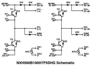
It combines 1kV silicon IGBTs and 1.2kV silicon carbide diodes in the company’s F5BP package.
Called NXH500B100H7F5SHG, it can handle continuous collector currents up to 210A (630A pulsed) (Tj = 175°C). Abs max power dissipation is 305W.
 To reducing stray inductance and thermal resistance, said the company, inside is a direct-bonded copper substrate and a copper baseplate.
IGBT-to-case thermal resistance is 0.198°C/W and, with thermal grease at the interface, 0.263°C/W chip-to-heatsink can be achieved. Thermal conductivity to the SiC diode die are 0.316°C/W and 0.405°C/W respectively.
Find the data sheet here
 Electronics Weekly Electronics Design & Components Tech News
I found surprisingly few explanations online of how the flying capacitor boost circuit worked – none of them good in terms of being readily accessible. I guess I need to find some time on LTspice.
It simply charges up two capacitors in parallel, usually from a third much larger capacitor, then ‘flies’ the second capacitor into a series arrangement with the first capacitor, hence giving twice the peak voltage. This then charges a fourth capacitor up to this voltage and keeps it there by switching at about 10kHz.
Compared with traditional switch-mode PSUs, there is less stress on the transistors, but the capacitors do age. In theory you are limited to multiples of the input voltage, but you can do tricks using smaller flying capacitors to achieve other voltages.