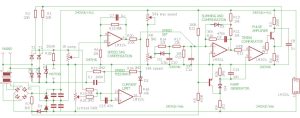
Approx circuit of DC-51 motor speed controller (D6 and D8 are probably the wrong way around)
And the more I looked at the circuit, the more I liked the speed controller.
I will probably change R28 from 25mΩ to 100mΩ to better match my 0.9A motor – the controller is set up for 4A max motors and the gain does not seem to be high enough as the motor resistance compensation cannot be moved into instability to fine-tune it, and the current limit works right up at one end. I will also probably alter the ratio of R17 and R21 to drive the motor up to its full 230V – at the moment it is 213Vmax with R8 shorted.
Update: I did change R28 from 25mΩ to 100mΩ. The current limit was much easier to set to 900mA, so well worth £1.70 for a 5W resistor. I was still not able to drive the motor into instability with the ‘IR’ control, wherever it was set, but will try operating the mill for a while to see of there is significant speed droop before the 900mA limit. End update
Safety note for folks not used to working with the mains: All electronic parts of this DC-51 motor controller circuit are connected to live mains and could kill you. This blog and its diagram could include errors.
How it works
The main power circuit is a simple two-thyristor-two-diode controlled bridge rectifier, powering the motor via a current sense resistor. There is no output capacitor, so the positive output voltage to the motor is thyristor-chopped full-wave rectified mains and bounces up and down from the mains neutral voltage to +380V (plus transients, the negative of which are eaten by D7). Note: a disadvantages of thyristor choppers is the electromagnetic interference created by the chopping action, so this circuit needs external filters.
It is to this very lively rail that the analogue control circuit is referenced to (which would be ‘0V’ nearly all other circuits). Despite its dynamic nature, for simplicity I have labelled it ‘240Vdc’ in the diagram.
The transformer with its associated bridge rectifier and four capacitors create plus (‘240Vdc+Vcc’) and minus (‘240Vdc-Vee’) rails around 240Vdc to run the quad op-amp and the rest of the circuit. The extra diode D1 is a small modification from standard – more of this later. I don’t know the values of the two Zeners. I think they are nearer 5V that 15V, but don’t know. BTW, there is a green LED on the unit running between 240Vdc+Vcc and 240Vdc via a 470Ω resistor.
Neatly, the current sense resistor is positioned between the controlled rectifier and the motor, so it provides a small positive voltage proportional to motor current referenced to 240Vdc for the control circuit.
The current limit circuit (see diagram) compares this voltage to an adjustable negative voltage using an op-amp wired as a comparator – unlike many op-amps, LM324 op-amps can be used as comparators (with common-mode caveats).
 Approx circuit of DC-51 motor speed controller, again
(Updated Mar2022, as are all the others in this page. Original had error around pins 11 and 12 of the IC)
March23 update: on reflection, D6 and D8 are probably the wrong way around.
The speed sag compensation circuit, can compensate the way motor brush and armature resistance slows rotation under load. It amplifies the current sense voltage modified by the ‘IR comp’ pre-set potentiometer.
A speed feedback path is established through R23 and R24, providing a signal proportional to the motor’s negative terminal voltage, which is roughly proportional to motor speed. Because of the 4.4MΩ resistance, and where it is connected, it provides a negative current with respect to ‘240Vdc’ that is near zero at zero revs and gets more negative as speed increases.
The variable speed set point is provided by the 10kΩ speed control potentiometer on the front panel of the unit and modified by assoicated components. In its original enclosure, the controller’s ‘stop’ contacts are connected to short potentiometer wiper and 240Vdc. R8 is included, I suspect, to prevent these contacts or the speed control from also shorting the 240V+Vcc rail if the max speed preset potentiometer is adjusted to 0Ω.
All four preceding circuits are bought together (via D3, R20, R24 and R17) at the ‘virtual earth’ (actually virtual 240Vdc) at pin2 of the op-amp, where their currents are summed to make a control voltage for the thyristor timing circuit – looks like there is some loop compensation around this op-amp as well.
The amplifier’s output voltage (pin1) rises to ask for less power and falls to request more power.
Because of diode D3 only pulling the summing point more negative, the current limit circuit can only affect the control loop in one direction: pushing pin 1 more positive to reduce motor current if it gets too high.
 That diagram again (D6 and D8 are probably the wrong way around)
In parallel with all above, the circuit around the pnp transistor is a zero-crossing detector, with D1 (mentioned above), R5 and R7 keeping the pnp ‘on’ the whole time except when the mains cycle is very close to it zero crossing when, twice per mains cycle, it turns ‘off’ briefly allowing R9 to charge C13 via the diode – resetting C13 to ‘240V-Vee’.
After this, over the half cycle, C13 discharges through R26 towards 240Vdc – this is the ramp generator for the thyristor timing circuit.
The timing comparator (op-amp pins 5, 6 and 7) compares the ramp with the summed-and-conditioned control voltage via R12, turning on the npn emitter follower current pulse amplifier when the ramp passes the control voltage. The pulse amplifier feeds the thyristor gates via R1 and R2 (BTW, R1 and R2 might be connected to T1 and T2 the other way around in the pcb).
Phew
Any comments?
The diagram was drawn with the help of the free version of Eagle PCB.
 Electronics Weekly Electronics Design & Components Tech News


I was just wondering if I could keep the controller from ever exceeding 30 volts to the motor . For safety reasons I don’t want it to be able to be turned up by the controller pot knob past 30 volts.
Hi K moore
Do not use this circuit if safety is an issue – it is not isolated, and much of it is at live mains potential at all times
It cannot be modified for ‘safe’ use.
I used it inside a fully-grounded all-metal machine tool designed to accommodate a controller with these characteristics, and took further precautions as the machine tool’s own safety precautions were out-of-date.
Please select a different, fully isolated, motor controller whose outputs are only ever at a safe potential.
hi
i may be wrong ,the fat diodes in the main power section should be reversed since they are connected with scr iin bridge mode.
Fantastic info especially on isolation. I want to control a potters wheel (wet!) on a 110v (+-55V) and was worried there would be an isolation transformer in place negating the 110V center tap earth.
Good to see this is not the case