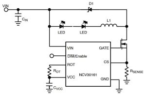
It is a buck converter – slightly up-side-down because it has its switch on the negative side.
There is no output capacitor, and the inductor and the leds are in series, so they both get the same current at all times.
Control-wise, it is a hysteric converter, with the main switch turning off when current in the inductor ramps up to one threshold, then turning on again after the current has ramped down to a lower threshold – this process repeats.
Usually, hysteric control is done using a pair of fast comparators (or one fast comparitor with a variable threshold) to monitor the inductor current (and therefore output current).
The cunning bit
However, in this case, the current sense resistor (see diagram) is only in the output current circuit during the ‘on’ period – and therefore only the off-point can be controlled conventionally (its comparator is set for a 220mV threshold).
To get the on-point, an external resistor is used to set an initial guess for the duration of the ‘off’ time.
As soon as the mosfet is switched on at the end of this guess (bringing the sens resistor back in circuit), the IC measures the current it actually achieved – comparing that to the 180mV it wants.
In the next cycle the timing guess is modified depending on whether the actual voltage was above or below 180mV.
And so it continues, around this try-measure-modify loop, which eventually gets the timing right, so that 180mV is measured just after the mosfet turns on.
If the input voltage later varies, this mechanism will track the off-timing will track to the correct point some number of cycles later.
For practical purposes (allow ringing to settle), the voltage measurement is actually made a little (85ns) after the mosfet turn-on.
A neat trade-off between internal and external complexity, while avoiding current sensing outside the supply rails.
Minimum off-time is typically 137ns and the IC will work with inputs across 8 to 40V, and down to 6.3V with reduced function.
Find the NCV30161 data sheet here for with another explanation of operation (but sadly little description of the modified-guess mechanism) and to see its other features.
 Electronics Weekly Electronics Design & Components Tech News


I do like the concept of hysteretic buck converters. I dealt with one such design at work for a number of years. One distinct advantage was the lack of concern about control loop stability and that sort of stuff. The down side was the relative unpredictability of switching frequency and the resultant effect on electro-magnetic emissions. With most switchers, you know what the fundamental frequency of the emissions will be, and while the magnitude of the harmonics is going to vary, at least you know where they are located on the spectrum. This seems like a low power application, so maybe it won’t matter? I’d keep the wires short, just in case. 🙂