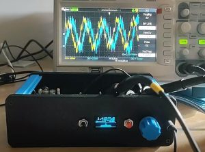
It is an up-to-30MHz software defined radio using a Raspberry Pi Pico for the local oscillator and… …. most of the rest of the radio.
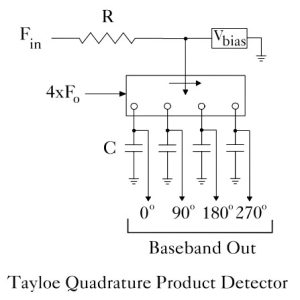
Very pleasantly, this design introduced me to a ‘Tayloe’ down-converter (after Dan Tayloe), which uses a cheap analogue switch and a pair of op-amps to mix RF down to I and Q at baseband.
The Pi microcontroller reads the op-amp outputs via its ADC, and puts out headphone audio – as well as controlling a display.
It is so clever that the local oscillator does not have to be right on the carrier, the software takes care of any difference – as far as I can tell.
This design is well worth looking at – find the surprisingly simple circuit on 101 Things, and check out the video for an explanation.
 And the original Dan Tayloe document (image left) is still available here on Northern California QRP Club website. Fin is the rf input.
What an interesting idea.
I love a good synchronous decoder, and went as far as building most of a 200kHz Radio 4 longwave receiver that used a phase-locked loop with its VCO running at 800kHz, divided by four to get 200kHz at 0, 90, 180 and 270°.
Each goes to one of the control inputs of a 4016 cmos quad analogue switch and (in a forgotten*) way, the synchronously-detected 200kHz carrier pops out out of one port with a 90° phase shift suitable for locking the PLL (using a multiplier-type subtractor) and the synchronously-detected audio pops out of a second port, with half the noise of a simple diode detector as detection is full-wave rather than half-wave.
Well, that was the idea – its other job was supposed to be to provide me with an accurate 200kHz frequency reference – I think the transmitter was locked to an atomic clock – and I also think the idea was finally killed when R4 longwave moved to 198kHz – it was that long ago….
Images:
screen shot of the Pi Pico SDR on the 101 Things YouTube channel
clip of Dan Tayloe document on Northern California QRP Club webside
– please get in touch if I have used either image inappropriately
 Electronics Weekly Electronics Design & Components Tech News


