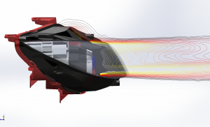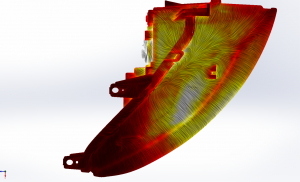
Figure 1: Surface plot showing temperatures and cut plot with stream lines of the flow inside the headlamp.
All of these new structural changes and components have caused the overall complexity of the headlights to explode.
And the choices offered in new models increase the variety of systems even more, adding to the complexity. For example, the new Audi TT comes with three choices of headlight systems (full LED, matrix LED, and Xenon). Ensuring the performance and reliability of the lighting system is not getting any easier with so much more complexity and variety.
The only constant in design to date is the thermal management aspect of the design. This task has to be handled with computational fluid dynamics (CFD) simulation software because creating prototypes for each change and different systems is inefficient and costly.
CFD simulations are traditionally done by analysts with specialised skills in advanced math and fluid dynamics, plus a command of the complex modeling tools required for CFD work. The CFD analyst has to assign grids to the solids and flow spaces, creating an optimised computing mesh. This mesh aids the engineer in setting boundary conditions and influences the solution convergence as well as accuracy of the result.
Mesh generation for a new lighting system can be very time consuming, and often even before the mesh in generated, a CAD model needs to be prepared to simplify the geometry for the mesh generation.
When you take a close look at the actual geometry of a headlight, there are a lot of fine details such as the saw-tooth structure of the light guides or small ribs on the reflector, or bezels for the stray light creation onto the road signs above the road, or the small facetted surfaces of the orange plastic of the turning indicator.
Such small structures are a pain in every traditional meshing process. But the worst part of it is when the mesh is finally completed after several days of manual work, the design is changed slightly before the first simulation is even run.
With the automotive lighting industry so strongly linked to the design, a better solution is required that is much more upfront in the design process and automates laborious tasks such as meshing and eliminates the geometry simplification.
Such a frontloading approach to create a highly accurate mesh automatically and directly on the native CAD geometry is incorporated in today’s CFD tools such as FloEFD, which is integrated with MCAD tools such as CATIA V5, ProE/Creo, and Siemens NX.
This approach enables design engineers to be up-to-date with the simulation on the latest design, and automatic meshing can dramatically reduce the manual workload.
Imagine you are a Tier 1 automotive supplier in the beginning stages of a new competitive offering to an OEM. The benefit of an upfront thermal simulation is that with a very rough design model you can already evaluate temperatures in that design.
Initial material selection can then go into the basic pricing calculations. Any change at that stage in the CAD model is directly up-to-date in the simulation project as well. This is basically the very first start where the software can be used, as soon as there is some CAD geometry available. It can later be extended to the fully modeled lighting system with all its features. For each design change, the simulation project is directly up-to-date.

Figure 2: Side view of a headlamp with a cut plot showing isolines of the mean radiant temperature radiating out of the headlight.
Thermal simulation is critical to avoid any damages of the system or light source caused by either environmental impacts, such as solar radiation, or a badly designed system.
A fan, for the cooling of the HB-LEDs, could create a thermal short circuit—that is when the hotter air that comes out of the heatsink from the HB-LEDs is sucked back into the fan and reused, drastically reducing the cooling efficiency. This results in an even hotter LED junction temperature and a damaged model. In the physical assembly, this is costly and time consuming, and unnecessary when the error can be easily caught within the simulation.
Of course, faster simulations should never come at the price of accuracy. The corresponding physics should be represented in the simulation and result in high accuracy. When considering simulation tasks in the automotive lighting industry, some critical criteria have to be met by the design.
First, thermal management—the whole system should work within its operating limits even in worse-case scenarios such as when a car is parked in Dubai with the engine running, lights switched on, and the sun shining into the lens of the Xenon module, potentially creating a focused solar hot spot on a plastic component at several hundred degrees Celsius. Such situations have to be resolved so as to not burn holes into the systems.
At the other extreme, situations have to be addressed, for example, when a car leaves a relatively humid warm garage after a rainy day and goes into the cold outside world the following day and a condensation film starts building on the front lens of the lighting system. This is undesirable to the OEMs, requiring that there should be no apparent condensation or at least it should vanish quickly.
Simulation tasks like these require certain capabilities in the software such as Monte Carlo radiation model with refraction capabilities, or condensation calculation where a transient simulation can provide information on how fast and in which areas the condensation will disappear the fastest and maybe even improve the evaporation with specific design changes.

Figure 3: Top view of a headlight’s surface plot showing the temperature distribution and the stream lines of the airflow close to the surface.
In a recent real-world example of a heat problem in an automobile headlamp, 14,000 cars had to be recalled when it was discovered that the headlamps could set the vehicle on fire because they are not adequately cooled when the car is not moving. In one actual fire, the car was idling on a dealer’s lot for about two hours when it burned up.
The fire was eventually traced to overheated, melted headlamps. The affected cars will be fitted with new headlamps redesigned to facilitate the escape of heat produced by the operating bulbs.
With the increased complexity of the models because of new styling opportunities with LEDs and the rapid changes in the design iterations that often happen incredibly fast, analysis and simulation tools must keep up, providing speed and sophistication to address complicated scenarios.
Today’s CFD tools are built to help design engineers understand thermal management and fluid flow in these complex systems, and to confirm the reliability of the system under all variable conditions to satisfy their customers.
Writer is Boris Marovic, industry manager for automotive, mechanical analysis division, Mentor Graphics.
 Electronics Weekly Electronics Design & Components Tech News


