- 1Vp-p to 200Vp-p
- 1Hz to ~1kHz
The exact zero crossing point is not important in this application, as long as some point in each cycle is transferred across consistently.
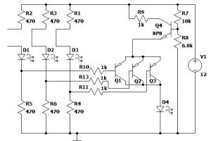
And this is what I came up with then (left, see that link for lots of info (waffle…))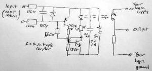
When it was time to transfer this from a prototype board to a pcb, I realised that I would have to include a switch for the floating 3V battery.
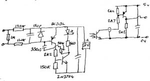
A bit of a re-think later, and a couple of wrong turns, I came up with circuit on the left of the top right diagram – essentially, there is a 330nf capacitor in series with the hysteresis feedback resistor and a 1MΩ resistor across the input to stop any temptation felt by the pnp to leak when the inputs are not connected to anything (although it still worked the same without the 1MΩ).
If anything, switching on the primary side was even cleaner with the feedback capacitor in the circuit. 330nF was a lying-around-on-the-bench choice ( I need a ‘floordrobe’-style phrase) and is not at all optimised. I know that 1nF (first loose-on-the-bench choice) was not enough and resulted in a very weird waveform – the feedback running out of steam part way through the transition.
Now current consumption with no input waveform connected is under 100nA – my meter resolution runs out at 100nA – so no need for a switch. The only thing that increases this current is if something is left connected to the base-side input, as pick-up through that will start the thing switching at 50Hz, where consumption is a few mA, maybe 4mA, which is also the consumption in operation if the waveform is roughly 50:50.
BTW, if I was doing this again, I might put a 1MΩ trimmer where the fixed 560kΩ feedback resistor is, as this arrangement is (I think) a bit too dependant on the gains of the two transistors and might want to oscillate.
The original single-resistor secondary-side (see diagram left above) proved a bit slow, with a rising edge of about 20μs and a falling edge of ~100μs (5V 2k7, or ~45μs with 470Ω) – by the way, Vce(sat) is ~1V.
It is not so much the power of the resistance to pull the output down, but the ability of the transistor to turn off that is the issue.
The optocouple used does give access to the base of the receiver transistor, but a resistor between that and its emitter can seriously reduce the sensitivity of the circuit.
Adding the pnp (2N213L) stage, with 2k2 base resistor, gave a nice crisp output with 1.4μs rise time and 3-4μs fall time.
The same circuit with the base hold-off resistor removed pushes this out to 10μs rise and a whopping 116μs fall.
As the base of the opto transistor is available, sending some positive feedback to that was a fleeting thought, but the photo trannie is on a ~200mm length of coax to keep the secondary end away from the dv/dt of the measured circuit, so routing any feedback was going to get awkward.
Updated update: the same pnp output amplifier with 470Ω in all three positions and running from a 5.8V rail yielded 300ns rise time and ~780ns fall time – measured at 10 and 90% (other values here are from first movement to somewhere near the appropriate rail on the exponential).
Oh well
Sadly, I needed <400ns rise and fall times to match the HC CMOS that is next in the circuit, so another rethink on the secondary side is needed.
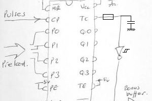
BTW, two simple inverters from a 74HC04 in series as a buffer from the old circuit (above left) resulted in nice clean 8ns transitions (up and down) but I could not trust that it would always be like that (and the intermediate node looked pretty ropey) . Adding a couple of resistors (of various values) around those inverters to add a bit of positive feedback gave horrendous oscillation during the transitions.
I shall order a 74HC14 hex Schmidt, and sort it all properly.
 Electronics Weekly Electronics Design & Components Tech News

