PCIe (Peripheral Component Interconnect Express) continues to gain popularity in the automotive industry to address the critical high bandwidth and low latency computing demands of distributed automotive architectures, but challenges for its widespread adoption remain. For automotive processors to take full advantage of this interface standard for shared processing, an automotive cabling interconnect must be defined that will help transform PCIe from an intra-electronic control unit (ECU) interface to an inter-ECU interface.
 Realising native PCIe over automotive cable channels (i.e., a combination of automotive cables and connectors) requires careful consideration of the physical interconnect. Electronics companies TI, Rosenberger and GG Group have proposed PCIe specification for automotive cable channels for vehicles, defining PCIe over cable channels.
OEMs and Tier-1 suppliers are rethinking the architecture of the automotive data backbone to support advances in both advanced driver assistance systems (ADAS) and vehicle connectivity.
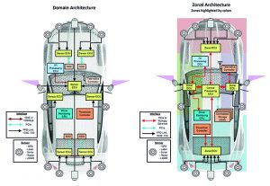
Rather than rely on computing to be implemented based on domains for example, the ADAS domain, the data backbones are shifting from domain to zonal architectures with the incorporation of local computing nodes, or zone controllers, to connect ECUs and interfaces based on location within their zone, regardless of their respective domain (Figure 1). These zone controllers then connect to a powerful central compute node that handles the data accordingly.
To enable distributed processing in zonal architectures, the automotive data backbone must employ high-speed interfaces that support high bandwidth and low latency. In particular, consideration for low latency must be taken when the shared data is used for safety critical, real-time processing. The PCIe ecosystem has already addressed these high bandwidth, low latency performance demands for industrial datacentres.
PCIe in vehicles
Realising PCIe over automotive channels involves careful consideration of the entire physical interconnect. The complete end-to-end channel (transmit-receive or Tx-to-Rx) link consists of two PCB channels at both ends of the automotive cable channel.
Each PCB channel includes the section from the Tx/Rx PHY to the corresponding PCB header. The automotive cable channel may consist of a single cable assembly, such as a bulk cable with two assembled connectors, or several cable assemblies. In the case of several cable assemblies, the cable channel includes inline connections. The limit for the cable channel length is determined by high-speed properties such as insertion and return loss in accordance with the channel limits over the required bandwidth.
Several tradeoffs are necessary to preserve the benefits of native PCIe while addressing OEMs’ needs for a common cable channel solution and minimised cable cost and weight.
One recommendation is to maintain a similar cable channel type to other high-speed interfaces. The cable assembly used for PCIe should be as similar as possible to other high-speed interface technologies such as 2.5/5/10GBASE-T1 Ethernet. In this way, OEMs need qualify only a single connector interface and cable type combination for a variety of high-speed interfaces throughout the vehicle.
Cable connection
To reduce cable count and weight, only essential high-speed in-band PCIe signals need to be connected over automotive cable and low speed, side band signals on the local PCB may be left unconnected. To reduce the risk of electromagneric interference (EMI) resonance, the 100MHz PCIe reference clock may be omitted from the cable interconnect. The PCIe specification supports separate reference non-spread and separate reference independent spread for independent clocking on either side of the cable.
Native PCIe transport requires dedicated Tx and Rx channels, meaning two-shielded twisted pair (STP) cables are needed per lane (one Tx, one Rx), resulting in a comparative increase from the single cable used by other high-speed interfaces such as MultiGig Ethernet. It is important to note that this trade-off in cable count preserves both native PCIe performance and a non-proprietary PHY interface over the cable.
To maintain similar PHY layer requirements, native PCIe implements non-return to zero (NRZ) signalling with dedicated Tx and Rx directions and has the ability to pass electromagnetic compatibility (EMC) requirements. NRZ signalling maximises the vertical eye margin compared to PAM-4 or PAM-16 modulation schemes. With dedicated Tx and Rx channels, it is not necessary to implement a separate automotive PCIe PHY to support full-duplex, bi-directional signalling interfaces where complex digital signal processors for noise and echo cancellation are needed.
Channel specification
It is important to determine the speed requirements of the PHYs for the link between the connections and to align them with the performance that the cables and connectors can offer. A channel specification is required to test high-speed channel parameters against those limits. Channel specifications describe the requirements for the cable and PCB channel based on S-parameters.
Key parameters are the required frequency bandwidth and primarily the insertion and return loss. Taking EMC behaviour into account, it is beneficial to specify screening and coupling attenuation. A detailed description of measurement set ups and procedures is also necessary to compare results.
The proposed automotive PCIe channel specification and a measurement set up and procedure description can act as a basis for a possible official PCI-SIG standardisation for automotive use cases.
The cable channel must support an insertion loss that is free of suck-outs, dips, or notches up to at least 10% beyond the Nyquist frequency of the highest transfer rate for safety margin across temperature, ageing and manufacturing processes. Table 1 shows the proposed cable limits.
Cable protection
Automotive qualification necessitates different ageing tests, such as long-term ageing for 3,000 hours at elevated temperatures, to characterise cable performance stability. Following all ageing tests, pre-defined critical high frequencies limits are expected to be maintained. Different cable design parameters, such as twist length, dielectric constants of the cores and isolation material selection must also be considered to meet interface performance requirements.
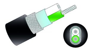 The GG 2Speed 251 STP cable could be a suitable automotive cable for PCIe 3.0. Shielding consists of aluminium–plastic foil that is wrapped around the two twisted cores (Figure 2). A copper braid is an additional shield and helps to meet the required EMC performance (screening and coupling attenuation) up to 4.4GHz.
The cable is suck-out free up to 5.0GHz, showing a notch at around 5.2GHz due to the cable construction. The notch is primarily affected by the lay length of the white and green wire. The cable also shows good performance against the proposed automotive PCIe 3.0 raw cable limit using the formula:
IL [dB/10m] = – (0.69f0.45 + 0.0027f)/15 where
• f = Frequency in MHz up to 4400-MHz.
Cables supporting higher frequencies are in development; prototypes of the 2Speed 256 meet the increased frequency needs of PCIe 4.0, with bandwidth to support a linear insertion loss up to 10GHz.
Rosenberger offers the high-speed modular twisted pair data (H-MTD) connector for differential signal transmission and the heavy frequency modulation (HFM) in case a coax transmission is preferred. Both systems offer 360° shielding.
Since return loss is mostly determined by connectors, the impedance along the H-MTD and HFM is precisely matched to the reference impedance of 100Ω and 50Ω, respectively.
Redrivers/retimers
Redrivers and retimers recover and counter-act the additional insertion loss and signal-to-noise ratio degradation that naturally occur when transporting PCIe over lossy media. Redrivers have been a part of the PCI-SIG integrator’s list of approved components since PCIe 2.0. Meanwhile, retimers have formally became part of the PCIe Base specification since PCIe 4.0.
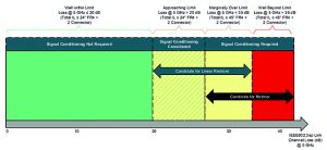
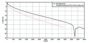 Table 2 shows a comparison between redrivers and retimers. For intra-ECU and short cable reach applications, linear redrivers are suitable. For native PCIe 3.0 transport, TI redrivers target applications of up to 5m using 2Speed 251 STP cable over Rosenberger H-MTD connector system.
For longer cable reach applications, retimers maximise signal margin. PCIe retimers offer more complex capabilities, including adaptive EQ, decision feedback equalisation and current divider rule compared to a redriver. Retimers also offer multiple link-monitoring diagnostic features to assist in system-level functional safety, including Rx link margining, internal eye monitoring and cable fault detection. For native PCIe 3.0 transport, TI says its retimers are targeting applications up to 10m using 2Speed 251 STP cable over a H-MTD connector system.
The following assumptions are used to estimate the maximum target cable length:
* PCIe specification insertion loss Rx limit for PCIe 3.0: 22dB at 4.0GHz
* At 4.0GHz, assume the following insertion loss (IL) characteristics in the link channel
* ILcable_m = 2Speed 251 STP cable: 2.75dB/m
* ILPCB = FR4 PCB trace: 4dB for 6” (152.4mm)
* ILconn = connector and additional PCB components: 1.5dB
* Estimated maximum cable length (m) = (ILtotal – 2xILPCB-2xILconn)/ILcable_m
 PCIe is an attractive interface for addressing critical high bandwidth and low latency computing demands by next-generation distributed automotive architectures. For processors to take full advantage of the PCIe interface for shared processing, an automotive cabling interconnect is required to enable native PCIe transport over automotive cable channels. In this way, physical layer designs will clear the path for automotive processors to realise their full computing, efficiency and connectivity potential.
Table 1: The proposed automotive PCIe 3.0 cable channel limits
Parameter/metric Proposed limits
Bandwidth 4.4GHz (1)
Insertion loss budget 26.4dB@4GHzz
Return loss budget 6dB@4GHz
Screening/coupling attenuation 45dB@4GHz /55.5dB@4GHz
Table 2: Comparison of linear redrivers and retimers
PCIe linear redriver PCIe retimer
Low-power consumption solution (no heat sink is required) High-power consumption solution (most cases require heat sink)
Ultra-low latency (100ps) Medium latency (less than or equal to 64ns based on PCIe 4.0 specification requirement)
Does not participate in link training but is transparent to negotiations between Root complex and endpoint
(Protocol agnostic) Fully participates in link training with Root complex and endpoint
(Protocol aware)
No 100MHz reference clock is required 100MHz reference clock is required
Helps with insertion loss Helps with insertion loss, jitter, crosstalk, reflections and lane-to-lane skew
CTLE is the typical equalisation circuit used CTLE, DFE and transmitter FIR are typical equalisation circuits used
Total solution cost is ~X Total solution cost is ~(1.3X-1.5X)
 Electronics Weekly Electronics Design & Components Tech News
