Look at any of today’s vehicles and you will be hard-pushed to find much left that is solely mechanical. With the push towards electrification it seems that every in-vehicle function has to be electrified too, from the camera-based rear-view mirrors to motor-controlled doors and tailgates. And, while the imagination of automotive engineers is broadening in terms of features and options, their demands for quality, reliability and long-term availability remain steady. The challenge with some of these applications is the high loads involved, especially with doors and tailgates, coupled with the volume of space to integrate them. This leads to challenges in power delivery and heat dissipation that have to be solved to a large part by the silicon vendor.
There are a range of comfort features that can add a touch of luxury through the support of an electric motor. Most common today are window lifters and sunroof openers. These need to provide around 12 Nm of torque. Sliding doors and tailgate lifters however require up to 140 Nm of force, demanding that tens-of-amps of current be supplied to the motor when in operation. On top of the enormous currents flowing there are the issues of heat dissipation, fulfilling electromagnetic compatibility (EMC) requirements, as well as ensuring that size and audible noise constraints are satisfied. Furthermore, such applications are required to achieve the necessary ASIL levels and fulfil the demands of ISO 26262 to achieve a functionally safe solution.
Design engineers, when reviewing the available components on offer, need to carefully consider how best to tackle the challenges they face. In an effort to reduce the space used on the printed circuit board (PCB), many semiconductor suppliers chose, sensibly, to offer integrated solutions. In the space of motor control, this typically falls into one of two categories: the integration of the microcontroller with FET drivers, or the integration of the FET drivers with the power switches.
With modern cars considered to require around 100 million lines of code1, automotive engineers have invested significant effort into their existing code base, development environment, and microcontroller platform. Therefore, it would be prudent to carefully review the potential advantages of any integrated microcontroller solution that was not already part of an existing project. With this in mind, it is more likely that innovative solutions in the space of integrating FET drivers and power switches will have more traction for automotive applications than microcontrollers integrating FET drivers.
Automotive pedigree that is steeped in tradition
Since 1974, Toshiba has been at the heart of delivering reliable electronic solutions that have enabled the automotive industry to deliver on the dreams of the vehicle-buying public. Early innovations delivered body applications such as wiper motor drivers, meter clusters, flashers, and door modules. Back then, these were based upon bipolar technology. A move to BiCMOS was implemented in the 1980s, forming the basis for a range of technologies that included 5V regulators, relay drivers and anti-lock braking systems (ABS). By bringing together bipolar, CMOS and LDMOS, BiCD technology formed the basis of silicon solutions in the 2000s, supporting the growth of several safety solutions including airbags, electric power steering (EPS) and applications mounted directly to the engine block. Over the past 45 years, Toshiba has delivered almost 2.5 billion ICs destined for automotive applications.
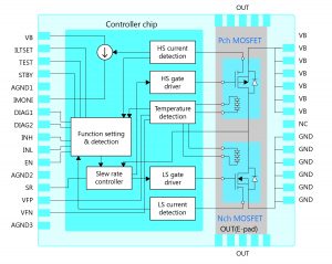
Continuing this heritage in automotive, Toshiba has been developing new solutions for 12 V motor control applications. The TB9111FTG consists of a high-side and low-side power FET with low on-state resistance and the corresponding gate driver controller IC (figure 1). The half-bridge operates in a temperature range of -40 to +175 °C valid for the power FETs.
Figure 1: Block diagram of the TB9111FTG
High integration for up to 50 A motor control
The TB9111 is implemented as a system-in-package (SiP solution consisting of three chips) in a 9 x 9 mm WQFN package. To optimize heat dissipation, the package has an Exposed Pad (E-PAD) on the bottom side. With an appropriate design, the half bridge can supply motor currents of up to 50 A.
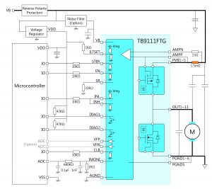
Figure 2: Application circuit including diagnostic evaluation, current monitoring and optional FET temperature monitoring for half-bridge operation.
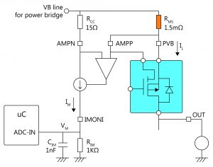
The control circuitry provides a wide range of features supporting both the control of the FETs as well as providing system protection and feedback to the microcontroller. Protection includes overcurrent shutdown, current limit detection, dead time generation, and undervoltage detection. An op-amp is also integrated that, together with a high-side low-ohmic resistor, provides an output that the attached microcontroller can use to measure current via an analogue-to-digital converter (ADC) (figure 3). The accuracy attainable here can reach 10%, depending on the approach taken.
Figure 3: Implementation of current monitoring via an ADC input and the IMONI output pin
To help combat the challenges of EMI, an external resistor can be used in conjunction with the SR pin to the desired slew rate (figure 2). The internal dead time generation automatically adapts to this setting. It should, however, be noted that slower rise and falls times have an impact on the upper end of the pulse-width modulation (PWM) frequencies that can be used. It also results in higher losses, generating more warming due to the higher power consumption. Therefore, engineers are advised to apply care when dimensioning this aspect of the circuit.
Control of the switches is provided by three digital inputs, two that provide the control, and one that provides an enable function. A further digital input offers control over the standby feature of the device, allowing the switch to enter a state that consumes just 5 µA of current. Two digital outputs provide diagnostic feedback to the microcontroller, the decoding of which depends on the state of the ILTSET input. The diagnostics focus on either over temperature or over current states, or can combine the two.
In order to keep temperature measurement lag to an absolute minimum, both the N and P-channel FETs feature integrated diodes for temperature monitoring by the controller chip. Temperature warnings are emitted at around 135°C on the die, while the device enters shutdown at 195°C, a state that requires clearing of this latching fault to restart. The temperature diodes can also be monitored by the microcontroller via two dedicated output pins through an ADC.
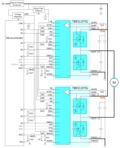
Both brushed and brushless DC motors can be supported. Brushed motors can be used with a single TB9111FTG, or two in an H-bridge configuration (figure 4). In this constellation, both high-side FETs can be current monitored. Alternatively, three devices can be combined to control a brushless motor.
Figure 4: Example full-bridge implementation with current monitoring in both half bridges.
Summary
The age of the electric vehicle demands deeper electrification of traditionally purely mechanical features in order to maintain the futuristic aura around the vehicle. This demands high-power motors combined with control electronics that can deliver the necessary torque to lift and move windows, doors and tailgates. Of course, it is also essential that a trusted partner, with pedigree in automotive applications, is chosen that understands the demands on reliability and quality to ensure these advanced features deliver, day-in, day-out, over the lifetime of the vehicle. Toshiba’s ongoing commitment to advanced silicon design is embodied in the TB9111FTG, making use of silicon processes and packaging technologies that provide their users with a powerful edge over the competition.
Klaus Neuenhüskes, Toshiba Electronics Europe GmbH
 Electronics Weekly Electronics Design & Components Tech News
