 In every sector, businesses are under pressure to make sure that the development phase of a new product’s lifecycle is completed as efficiently as possible. Awareness of the potential impact on supply chains of geopolitical events means there’s a need to get designs right first time to stay one step ahead of competitors.
At the heart of that is the test and measurement process. As electronic devices and the systems that incorporate them become more sophisticated, more complex testing is demanded. At the same time, there is a need for efficiency to address sustainability targets.
The consequence for development engineers is the same, whether working on electric vehicles (EVs), industrial robots, household appliances or components for renewable energy systems. There is a need to analyse a wealth of both mechanical and electrical data as efficiently as possible in order to fine-tune critical development decisions.
The increasing mainstream adoption of EVs is accompanied by electrification of other forms of transport, from trains to ships and aircraft. Developing and optimising the efficiency of electric motors and motor drives has never been more important. Engineers need to be able to accurately measure and understand how every component performs at each point in what can be a complex powertrain system.
Components may have been tested previously, but once they are brought together in an ecosystem, a more complex approach is needed to ensure they are working together for optimal efficiency. It is also important not to neglect the potential impact of other features included, in even a mid-range, new family car that relies on an electrical supply and could affect performance.
EV powertrain testing
Powertrain system testing typically encompasses multi-channel DC and AC analysis and physical parameters such as rotational speed, mechanical angle, temperature and even vibration.
Assessing the performance of systems with variable-frequency drives is a four-step process that looks in detail at the efficiency of the inverter and motor efficiency as well as the overall system. Accurate measurements need to made of the three-phase input power to the drive, DC bus voltage, motor input power/drive output power, and the mechanical power of the motor itself.
For EVs and other applications that supply the drive system with a DC source, the process and measurement points are the same, but with no ac-dc conversion stage within the drive that element is omitted.
Combining forces
In the power electronics industry increasing demand for next-generation devices using silicon carbide (SiC) technology is driving a need for ever greater precision in measurement. Testing EVs and SiC/GaN inverters calls for versatile instruments. An example is the DL950 ScopeCorder, which combines the features of a mixed-signal oscilloscope with those of a high-speed portable data acquisition recorder. It can be brought into play at all stages of powertrain testing, where it can capture multiple electromechanical signals simultaneously to provide insight into the dynamic behaviour of any system or device.
Pairing with another instrument, for example, a high speed, high resolution oscilloscope, can provide even further information on waveforms; used with a power analyser, it can verify power consumption with low uncertainty.

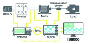
Figure 1: An integrated software platform can integrate timing, control and data collection across several instruments
EV powertrain testing, for example could involve a ScopeCorder at the start of the process with an oscilloscope and power analyser to measure initial input. With an oscilloscope it accurately monitors the inverter, then with a power analyser provides data between inverter and motor that enables drive efficiency to be calculated. Combining it with a power analyser between motor and load gives an insight into motor efficiency.
Observing small changes in high- speed signals accurately is particularly useful for teams working on next-generation inverters who want to detect phenomena that can cause unexpected anomalies, for example.
A high vertical resolution, mixed signal oscilloscope allows users to observe even the smallest of changes such as overshoot and ringing in fast-switching power signals. It can also provide data on switching losses, logic control of the motor drive/inverter and help with debugging of serial buses.
A high accuracy power analyser gathers raw waveform and numeric measurement data to be sent to the test bench software where any anomalies can be investigated. This allows developers to verify the efficiency of individual components as well as the complete drive/powertrain when driving or regenerating kinetic energy.
Optimal testing
For testing new products, engineers want to spend the minimum amount of time setting up equipment in favour of devoting time and effort to seeing how a design performs.
Co-ordinating data from different instruments to look at a product’s various characteristics can be challenging. Finding correlations requires time signals to be synchronised and engineers may need to be able to operate more than one type of software.
For example, testing motors and inverters for vehicles, elevators, air conditioners and power-generating equipment often involves using several instruments. While oscilloscopes offer high sample speed and in-depth views of waveforms a power analyser provides insight into power efficiency, but is optimised for accuracy of power reading rather than capturing the detail of waveforms that can provide useful insight into how the system is operating.
Real-time overview
Bringing together measurements from multiple instruments in real time provides a detailed overall view of system performance. An integrated software platform, for example the IS8000, can addresses this challenge by making it straightforward to tightly integrate timing, control and data collection across several instruments. It can remotely operate and record data from the company’s DL950 daq system, DLM5000/DLM5000HD series oscilloscopes and WT5000 power analysers, all of which can be monitored and configured from the software. This measurement suite presents on a single screen an insight into the timing of control signals and switching events and how products being tested react to them.
This level of synchronisation is made possible by the IEEE1588 PRP Precision Time Protocol, which is used to synchronise clocks throughout a network at a sub-microsecond level. With a single endpoint acting as the source, the protocol transfers the reference time through various switches and routers to other endpoints.

Figure 2: Measuring the efficiency of an EV motor using multiple instruments
Figure 2 illustrates measuring the efficiency of an EV motor using the ISO8000 platform to time correlate data from a power analyser (WT5000) and DL950 ScopeCorder with less than 10μs error using IEEE1588 PTP technology.
Situations such as design and testing of drivetrain systems for EVs illustrate the advantages of linking together multiple devices. Even small improvements in efficiency can result in increased range, but measuring efficiency requires accurate synchronous measurement of power, motor speed and torque.
Control of devices
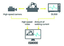
The ability to control third-party high-speed cameras and modbus devices makes it easier to operate and manage instruments for measuring power, physical phenomena, video and control signals. In the case of the IS8000, for example, the camera and daq systems share only the trigger signal, meaning that video image and waveform data can be captured individually when analysing mechanical processes such as combustion cutting and vibration before being precisely matched.

Figure 3: Analysis of a robotic welding control system
This is useful in robotic welding, for example, which involves simultaneous recording of multiple signals. As well as the movement of the robot arm itself, data has to be captured from sources including the power supply, control unit and communications network. Video, which is time-synchronised with waveforms and control signals, can be viewed in slow motion playback alongside electrical and mechanical information to understand dynamic behaviour that would otherwise be too rapid to observe.
Developing and evaluating systems for solar and wind power also requires being able to see how different aspects of performance change alongside each other. It is important that renewable energy devices maintain their efficiency through a series of power conversion stages, requiring multiple measurement points to obtain a full picture of dynamic behaviour. Synchronising waveforms from multiple instruments gives engineers insight into individual components such as control units, solar panel arrays or generators as well as an overview of the whole system.
 Electronics Weekly Electronics Design & Components Tech News


