 Renewable energy initiatives are on the rise around the world. Countries are adopting comprehensive plans to reach ambitious solar reliance goals within the next decade. The trend drives new demand for equipment such as solar inverters and pushes engineering partners to innovate sensors that satisfy creepage distances and switching voltages of high-power photovoltaic applications.
Solar changemakers are opting for reed switches and relays. Other ‘always-on’ electrified sensors require constant power, but not reeds. This type of sensor does not draw power while in its passive state, reducing energy consumption to zero.
How reed relays work
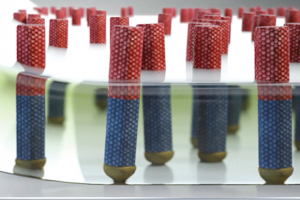
At the heart of a reed relay is a reed switch, where two ferromagnetic blades, or reeds, sit slightly separated. A magnetic field draws the two reeds together. The switch sips only a small amount of power in its ‘on’ phase – or when the two reeds meet to connect the circuit.
Even those who do not know much about reed sensors probably use them without realising it. For example, a reed sensor detects which seats in a car are occupied. The reading affects seatbelt warnings and airbag deployment. They are also on e-bikes, sensing whether a kickstand is deployed or if it is tucked in and the bike is ready to ride.
Similar to a reed switch, a reed relay triggers based on the presence of a magnetic field, but instead of awaiting an approaching magnet, a coil envelops the switch’s glass casing. When the voltage running through the coil reaches a certain threshold (up to 1,500V for a solar inverter), the reed switch activates.
Reed sensors are a popular choice for alternative energy projects for several reasons. The economic energy usage maintains sustainability goals; the high voltage designs are optimal for solar applications; and they are hermetically sealed against outdoor battering of rain, dust and wind.
A solar case study
A leader in renewable energy systems for solar inverters in large-scale commercial and industrial facilities was considering an electromechanical relay. Instead, a collaboration resulted in an energy-efficient, longer-life reed relay.
There were two requirements: the reed relay needed to have a high power 1,500V switching voltage; and a large creepage distance of 15mm.
The sensors would monitor isolation resistance and potential induced degradation (PID). These are two factors that can diminish performance of a solar inverter and cause serious harm if improperly monitored.
A particular design was optimal for products requiring <1,000V switching voltage. The solar energy system supplier collaborated on a fully customised KT relay. Two reed switches were produced to meet the design specifications and also “significantly improved product lifetime over an electromechanical switch”.
Higher switching voltage
One concern with a higher switching voltage is arcing. To accommodate the 1,500V and eliminate potential degradation, the client required a larger creepage distance measuring 15mm.
The higher the voltage, the larger the creepage distance between conductive parts. Because of the 1,500V inverter, the client needed a 15mm creepage distance to maintain safety and performance.
The existing coil was redesigned to switch faster than before, eliminating arcing over the large creepage distance.
Hermetically sealed
Solar equipment is located outdoors and is subject to endless heat, dust, rain and dirt. The switch itself is kept safe inside a glass container filled with a protective gas, such as nitrogen. To further prevent corrosion and other hostile elements, it is commonly potted or encased.
The most common threat to power efficiency is electrical current leaking into the ground. This is something renewable energy pioneers cannot afford. Using two sensors has three benefits. The first is that one sensor checks isolation resistance before connecting to the power grid and the other PID, to ensure consistent performance. The design protects users and equipment against electrical shock.
Longer lifetime
The higher-power coil required new testing procedures to ensure it could still meet product lifespan criteria. (Previous tests evaluated only switching voltages up to 1,000V.) The new range of tests was drawn up to guarantee reliability for years to come.
Using the manufacturer’s facilities to analyse product performance over a relay’s lifetime, test its safety and evaluate switching cycles to all international standards, a new test was designed to make sure the higher-power coil was capable of the demanding role in solar power systems.
 Electronics Weekly Electronics Design & Components Tech News
