 Microchip has turned to silicon carbide to create a bi-directional electric vehicle on-board charger design for 400V or 800V batteries.
There are two halves: a 7.6kW bi-directional two-phase interleaved totem-pole power factor corrector, and an 11kW dual full bridge transformer-coupled bi-directional dc-dc converter.
“These two designs work together,” Microchip told Electronics Weekly. “At PCIM we showed both operating in bi-directional operation, continuously charging and discharging a load of super capacitors – the three-phase PFC stage created a dc link voltage of 650V.”
Full details are only available to “qualified companies”, said Microchip, but the limited information offered so far reveals a pair of development boards implementing designs which can be modified for different input, output and intermediate voltages:
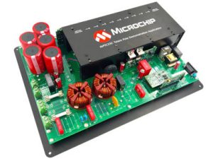
Totem-pole power factor corrector (above and left)
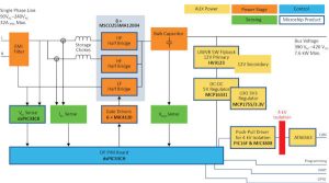
The power factor correction stage connects to main power between 90 and 265V (47 to 65Hz) and can handle 32A (or 16A with one phase). On its other side, the development hardware appears to be set-up for a 400V dc bus to which it can deliver 20A.
Known as a ‘bridge-less’ design for its lack of diode bridge, it has a full-bridge of transistors with 50-60Hz switching in the half-bridge on one side (‘LF’ in diagram) and, in this case, 100kHz switching in a pair of phased half-bridges on the other. Up to 98.5% efficiency is expected.
Forced air cooling is required for the 334 x 420mm development board, and operation is across -40 to +65°C.
It “contains modular hardware and firmware to enable operation in PFC and inverter modes”, said the company, telling Electronics Weekly: “There is full software support for all programmable devices in this design. The code is fully accessible and, once generated, users can extend and modify the code as they wish.”
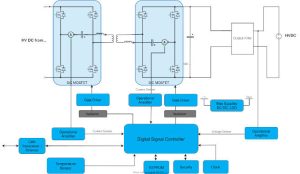 Dual bridge bi-directional dc-dc (right and below)
The dc-dc stage development board is set-up to expect a expect a 700-900V bus on one side (the input when charging) and an 800V battery. Both sides are rated at 17A. Switching is again at 100kHz, and up to 98.5% efficiency is expected.
An isolated CANbus is included for communication.
Forced air cooling is required, and operation is across 0 to +50°C.
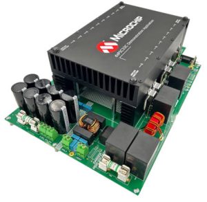 It has “non-linear adaptive control algorithms for improved performance” according to Microchip.
The company’s own SiC mosfets (in surface-mount D2PAK), microcontrollers and other components are used in the designs, many of which are AEC-Q100-qualified. Depending on voltage requirements, 700, 1,200 or 1,700V SiC mosfets are specified.
On top of the price of the kits, how much does the customer pay?
“Based on the support needed, Microchip handles this on a case-by-case basis,” said Microchip.
Find limited information on the two demonstration boards and the bi-directional on-board charger on this web page.
 Electronics Weekly Electronics Design & Components Tech News
