“In recent years medium power power supplies are required to provide a level of reliability and precise control that is difficult to meet with analogue-only configurations,” said Rohm. “On the other hand, while fully digitally controlled power supplies enable fine control and settings, they are not widely adopted in the small to medium power range due to the high power consumption and cost of the digital controller.”
Aimed at industrial PSUs between 30W and 1kW and dubbed ML62Q20xx, its MCUs “provide the same functionality as fully-digital control power supplies at low power consumption, and cost equivalent to analogue power types”, it claimed.
There are four parts, with 16 or 32kbyte of programme memory, in a 6.5 x 6.4mm 20pad TSSOP or a 4 x 4mm 24pad WQFN. All get 2kbyte of data ram and 4kbyte of data flash.
The 16bit CPU is a 16MHz nX-U16/100 (A35 core) from Lapis Semi, which Rohm owns. An on-die phase-locked loop creates a local 64MHz clock for pulse generation.
Aside from seven timers, the ICs have a five channel 12bit 1.375μs ADC, voltage reference, programable gain amplifier (4x, 8x, 16x, 32x), three analogue comparators and two 8bit DAC channels. For functional safety, there is RAM parity error detection, ROM-unused-area-access-reset, a watchdog, ADC test, UART loop-back, I2C loop-back and GPIO test.
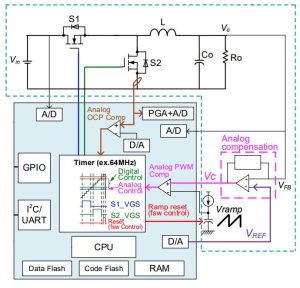
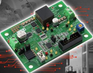 The evaluation board, called both ‘LogiCoA001-EVK-001’ and ‘REF66009’, implements a 160kHz synchronous dc-dc buck converter which takes in 12 or 24V (8 – 38V) and outputs an adjustable 1 to 8V at up to 5A.
Input and output voltage are monitored by ADC channels, main switch current is monitored by another ADC channel and, for a fast fault response, one of the comparators.
DAC outputs are used to produce the set voltage for the external error amplifier (giving the MCU its first lever to pull to control the dc-dc converter) and a reference for the fast-response over-current comparator.
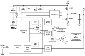
The voltage feedback loop uses analogue compensation around the external error amplifier, and the resulting voltage is fed into a comparator inside the MCU whose output controls the ‘on’ time of the main mosfet switch.
The other input of that comparator is a repeating voltage ramp, which the MCU controls (its second lever) as it is generated across an external current-fed capacitor that is periodically shorted by an MCU-generated pulse waveform.
“The use of a microcontroller allows many parameters such as the output voltage setting value, dead -time setting value and protection circuit setting value to be changed by the software in the same way as the full digital control,” said Rohm, which also conceded: “Although the response characteristics of the output voltage are inferior to full digital control due to the use of an analogue compensator for output voltage control, it is not a significant demerit as it can realize sufficient response characteristics as a general switching power supply device.”
The software also allows non-volatile factory calibration values to be stored, errors to be logged for future analysis, and can be used to implement adaptive control of parameters such as dead-time.
Find the ML62Q20xx family data brief here, and the eval board web page here – from which a user guide, excellent application note and software description can be downloaded, which are all worth a look.
 Electronics Weekly Electronics Design & Components Tech News
