The first three devices in the planned TCR1HF series, available today, are TCR1HF18B, TCR1HF33B and TCR1HF50B with fixed outputs of 1.8V, 3.3V and 5.0V respectively. Devices are in the pipeline at 2.5, 2.8, 3.0, 3.1 and 3.2V.
Maximum drop-out over the -40 to 125°C operating range is 1.06V at 150mA for the 1.8V version, falling to 660mV for the 5V part. The output limits at 200mA over temperature (300mA 25°C). These figures are when supplied with 24V.
Despite those drop-out figures, which are from the data sheet, the device is specified to operate at 4V minimum – Electronics Weekly has asked why, so watch this space.
Maximum survivable voltage on the supply pin and the control pin are 40V, and max power in a 25.4mm square of FR4 board is 580mW.
Quiescent current is typically 1μA (1.6μAmax over temperature at 24V) which drops to 480nAmax over temp when the control pin is used to disable the IC.
On the subject of the control pin, Toshiba said: “Depending on the Vin voltage and application speed, Vout voltage may occur due to leakage current even when control=low [output disabled].” Changing the output capacitor or input slew rate are proposed countermeasures if evaluation shows this happening.
The necessary external capacitors can be ceramic, and with a 1μF output capacitor output transients are typically -60mV or +50mV with a 1μs load step from 0 to 10mA or back.
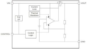
Protections include over-current and thermal shutdown.
Packaging is 2.8 x 2.9 x 1.1mm SOT-25 (called ‘SMV’ by Toshiba).
 Electronics Weekly Electronics Design & Components Tech News


