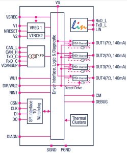
Called SPSB081, its aim is to provide a companion microcontroller with power, two serial interface transceivers, battery-voltage high-side load drivers and power for its peripherals.
There are four devices giving 5V or 3.3V from the 250mA LDO, and either with or without the LIN transceiver. In each case, the company told Electronics Weekly, the 100mA LDO can be set to 3.3 or 5V via the SPI bus.
| 250mA regulator (V1) |
LIN interface |
100mA regulator (V2) |
|
| SPSB0815 | 5V | yes | 3.3 or 5V |
| SPSB0813 | 3.3V | yes | 3.3 or 5V |
| SPSB081C5 | 5V | no | 3.3 or 5V |
| SPSB081C3 | 3.3V | no | 3.3 or 5V |
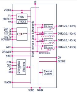 …C.. versions loose the LIN interface
Intended to power LEDs and sensors, the four high-side drivers can source up to 140mA and can be pulse-width modulated to 10bits.
The high-side outputs have current monitors, and there is open-load diagnosis for all outputs, said ST.
The two main power inputs – VS and VREG in the diagrams – operate up to 28V and can survive 40V for 400ms for load-dump protection.
“The power sources and transceivers available on-chip help simplify the design of car-body controllers for a sunroof, seats, tailgate, doors, and lighting modules,” said ST. “The ICs provide multiple standby modes with low quiescent current and programmable local or remote wake-up to help minimise power consumption.” Shut-down quiescent current is typically 15µA, it added.
Within the devices is a significant amount of monitoring hardware for fault detection and diagnosis, with a separate output pin for fail-safe signalling.
“These features support use in applications that must satisfy functional safety requirements in accordance with ISO 26262, even if not designed as a safety hardware element,” said ST. “All outputs feature over-current protection and open-load fault indication. The primary LDO [V1] features over-voltage protection and thermal protection, while the secondary LDO has over-load, over-temperature, short-circuit and reverse-bias protection. Both have short-to-ground monitoring at start-up and continuous regulator-failure monitoring.”
Over-temperature response is staged: initially keeping V1 power and the CAN receive channel alive so that the host MCU can log faults, and then shutting everything down if temperature increases further.
The family is AEC-Q100 qualified, specified from -40 to +150°C, and able to operate up to 175°C.
Packaging is 5 x 5mm thermally-enhanced QFN32L.
The CAN interface is flexible data rate and compliant to ISO 11898-2/2016 and SAE J2284. The LIN interface is complient with ISO 17987-4/2016.
Use is also forseen in gateways, air conditioning controllers, keyless entry systems, telematic controls and control panels.
Find a web page for the SPSB081 IC series here
 Electronics Weekly Electronics Design & Components Tech News
